Variable Shell Thickness Example
This example shows the process of creating an extruded polysurf (multiply attached surfaces), assigning a different thickness to each surface, shelling the surfaces, and capping off the ends with the Skin/Loft command.
Step 1. Select the Curve-Add Curve command and add a curve like this to one of the views. When you enter a point on the curve with the left mouse button, it goes in as a “smooth” curve point. You can override this by picking a curve point using the ‘k’ (knuckle) key on the keyboard. In this example, the first two points (from the left) were entered with the ‘k’ key and the rest were entered using the left mouse button.
Step 2. Select the Create 3D-Extrude Surface-Extrude Straight command and then pick the curve created above. You will be prompted with a dialog box asking for the length of the extrusion, perpendicular to the current view on the screen. Just for the example, enter a number here that is about equal to the width of the curve. For this example, I changed the number of rows to 3 and selected the OK button. This means that the extruded surfaces will contain 3 rows along the length of the surface and allow you more flexibility in shaping the middle of the surface. You should see something like this below in the 3D View.
Note that these two surfaces are “bonded” together and can be edited at any of the surface defining points (little squares), even at the bonded edge. Also note the use of edit points that lie on the surfaces. This cleans up the screen and makes complicated surfaces easier to edit. For this display, I also changed the Row and Col Divisions of each surface to 5X5 to make the surface shape more visible. You can change surface attributes by “right-clicking” on each surface.
Step 3. “Right Click” on each surface to display its attribute dialog box. Enter a different surface thickness for each surface and pick the OK button. Keep the offset thickness relatively small compared to the size of the surface.
Step 4. Select the Create 3D-Shell/Loft Surface command and pick either surface. This shell command will create offset surfaces for both (bonded) surfaces at the same time. When you pick the surface, the program will display a dialog box allowing you to override the predefined surface thickness with one overall thickness. Ignore this feature and just pick the OK button. You should see something like what is shown in the next two pictures.
This is the end view of the two shelled surfaces. Note the different offset thicknesses and see how the program extended each surface to make sure that the offset surfaces are joined and bonded together. This means that you can edit the offset surfaces just like the regular surfaces. Keep in mind that for most real applications, there is no such thing as a “mathematically exact” offset surface, especially if you want the offset surfaces in a form that you can edit. If the offset thickness is small compared to the size and curvature of the surface, then the result should be well within building tolerances.
This is a hidden line 3D view of the surfaces. [See View-3D View-3D Options and check the Hidden Lines box.]
Step 5. Select the Create 3D-Skin/Loft command. This command will allow you to “cap off” the ends of the surfaces. This command has to be done twice, once for each set of two offset surfaces. First, display the surfaces in 3D view. This will make it easier to pick the edges of the desired surfaces. Next, pick the two end curves of the rounded surfaces. You need to pick the two edge curves near the same end of the surface so that the skin command knows how to connect the two surface edge curves together. After picking the two curves [the program will highlight the edges as you pick them] with the left mouse button, press the right mouse button to tell the program that you are done selecting curves to skin. The program will display a dialog box with a number of options that will guide the skinning process. Just take the default options and pick the OK button. After using the Skin/Loft command on the two sets of surfaces, you should see something like these two pictures below.
Hidden line view of the variable thickness offset surfaces with the ends capped off.
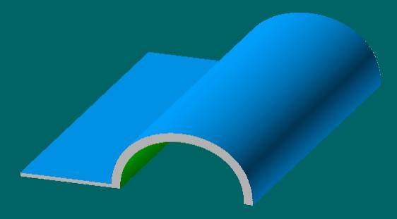
Rendered view of the variable thickness offset surfaces.
Keep in mind that this model contains NURB surfaces that are all “watertight” and bonded together, which means that you can move any edit point without introducing leaks or causing the surfaces to separate. You do not have to un-bond or “explode” the surface edges to be able to edit their shapes.