Simple Plate Layout Example
Sometimes it's hard to see exactly what you have to do to use a program. There are a lot of pretty pictures and lots of flash, but exactly how do you do it? This example tries to boil everything down to a simple 1, 2, 3 formula for getting an unwrapped (developed, or layout) pattern from a 3D surface.
(There are many other ways to use our program. This is just one of the most common methods.)
Goal: I want to define a 3D surface using just two opposite edge curves. This will be the surface to unwrap.
Step 1. Define the two edge curves. If you are familiar with another CAD program, the easiest way is to define the two curves in that program and transfer the curve shapes to Pilot3D using the common DXF file transfer format. You can read in the DXF file using the File-Data File Input-DXF Input command.
However, Pilot3D has a very easy way to define curves using its Curves-Add Curve command. You use the left mouse button to enter each point and the right mouse button to terminate the curve. If you want to set any of the input edit points to a specific measurement point, right click on the point and a dialog box will appear. This box allows you to set the exact X,Y,Z measurement values of the edit points. Sometimes people want to set the exact locations of the end points of the curve, but change the shape of the middle of the curve. Once you have defined the curve, you can move or drag any of the edit points using the Edit-Move point command. (It's also on the toolbar.)
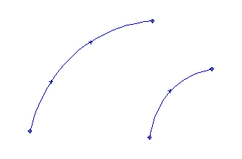
Two curves defined showing edit points
Step 2. Once the curves are defined just the way you want, select the Create 3D-Skin/Loft Surf command. This command will stretch a surface between the two curves. (Actually, it can fit a surface across many cross-section curves.) Use the left mouse button to pick the first curve and then pick the second curve. This can be done in any order, but you should make sure that you pick the curves near the same or common ends. Once you have picked the two curves, press the right mouse button to pop up a dialog box. This box allows many options, but for most cases, you can just pick OK.
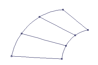
Surface created between the two curves
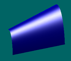
3D rendered view of the surface
Step 3. Now you are ready to unwrap or develop the 3D surface into a 2D pattern. This is done with the Develop-Develop Plate command. Once you have selected this command, use the left mouse button to pick any curve on the surface. A dialog box will appear with many options that you can ignore for most cases. Pick the OK button and the unwrapped 2D pattern will be displayed.
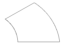
2D unwrapped pattern of the surface
That's all there is to it - one, two, three. Oops! the fourth is to use the File-Data File Output-DXF Output to send this shape to a DXF file that can be read by any CNC cutting CAM software. The only thing you have to be careful about for this step is that the DXF output dialog box has to be changed to output the current 2D view of the pattern, not the full 3D model shape.
That's it.
HOWEVER, if you think that the surface created between the two curves has a lot of twist or double curvature, you might have to go back and alter the shape of one or both curves. You can check for twist in a surface using the Surf-K_Patch-KPat All command. This command displays the Gaussian curvature of the surface in color. The color relates to how much twist there is in the surface.
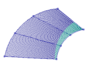
Gaussian curvature of example surface
Dark blue indicates that the surface is perfectly (or nearly) developable. Light blue means that it has a little bit of twist, but it is probably OK. As the colors change to green, to yellow, and then to red, the twist in the surface goes up and the program may not be able to unwrap it to get a 2D pattern. Or, the program might find a 2D pattern that cannot be stretched (some say tortured) into its 3D shape. There are no exact answers here for deciding whether a surface has so much twist that it cannot be built. To learn more about the details of unwrapping developable and non-developable surfaces, see our white paper called "Plate Development and Expansion".
For those surfaces with twist we do have a unique way to edit the shape to eliminate the twist. This is our "ruling line" approach. Rather than skinning a surface between the two curves, you tell the program to calculate ruling lines (perhaps 50) between the two curves. Each ruling line is color encoded (just like the Gaussian curvature) to show how much twist there is in the surface at that point. This allows you to move (drag) any of the edit points on the two curves and dynamically watch how the ruling lines change shape and color. See Surface Development and Layout for examples of the ruling line technique.
Still another problem is the need to subdivide a larger, twisted surface into smaller sections that can be unwrapped or that will fit the material you are using. Pilot3D has a command that allows you to define curves ON the big surface so that you can define sub-surface areas.
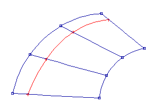
Same surface with curve attached
You can use the attached curve and the edge curve to create a smaller sub-surface that can be unwrapped.
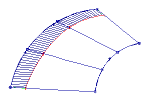
Surface with sub-surface defined
This sub-surface can be unwrapped just like any other surface.
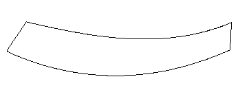
Unwrapped sub-surface 2D pattern
This surface subdivision and layout can be applied to awnings, tents, sails or any complicated shape. Anything is developable if you break it down far enough.
Well, this was supposed to be a simple example, but I got carried away at the end. I just wanted to show that Pilot3D can take on even very complicated jobs - when you're ready.