Creative 3D Architecture
Stephen M. Hollister
This is a (relatively) quick intro for using Pilot3D
to explore creative 3D surface architecture.
There are many ways to create geometry with Pilot3D,
such as sweeping, extruding, and lofting surfaces. This tutorial, however, will
focus on creative 3D architectural design starting with our basic shape
building blocks: boxes, triangles, cylinders, cones, spheres, and ellipsoids.
Remember, these are starting shapes only – your imagination is your only limitation.
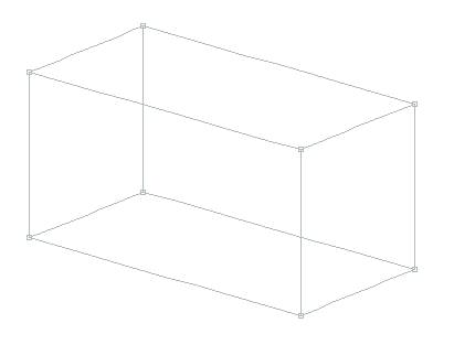
Most all of these basic shapes are found in the
Create 3D pull-down menu. Let’s start with the basic box. You can create the
box below using the Create 3D-Box-Dialog Input command and picking the OK
button. This gives you the standard, default box starting shape. There are many
other options available when you define this box, but let’s start with the
simple box and see where we can go from there.
Pilot3D uses NURB (B-spline) surfaces to describe geometry. NURBS are surfaces that are defined by a rectangular grid of points, often connected and called rows and columns. You may have heard about NURBS or B-splines and their vertex points that do not lie on the surface, but, in Pilot3D, we use NURB edit points that lie on the surface. (We hide all of the messy vertex points.) You can see this in the above model where the box is made up of 6 NURB surfaces and all of the row and column defining or editing points are located on the surfaces. (We have been doing this for about 20 years now and these points that lie on the surface are one of our biggest selling points.)
You also need to realize that Pilot3D also creates this box so that all of the edges are bonded or glued together. This means that if you move any of the edit points that are common to two surfaces, Pilot3D will update both surfaces at the same time. Of course, you say? Well, many other CAD programs call these things polysurfaces and do not allow you to edit them unless the surfaces are “exploded”. Then, if you edit the surfaces, they separate! This doesn’t happen in Pilot3D, which makes sure that all surfaces remain connected and “watertight”. As you will see, the edit points on the surfaces and the bonding of surfaces will make your creative design process much easier.
Please note that designing will be done in the wireframe views, but you can keep open a “Render View” to see a more realistic view of the shape, as shown below.
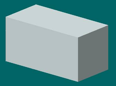
You can display this view using the View-Render View-Open Render View command. You can cascade or tile this view or just minimize it to get it out of the way.
If you are following along with this tutorial in Pilot3D, I need to make a comment about CAD programs and windows and views. Pilot3D starts up by showing four windows for four different views of the design. We do this because we were told that that is what everyone expects to see. Well, I don’t like it. I prefer to work in one view at a time, maximized, so that I can see what I am doing. I use the buttons on the toolbar to switch between views. If you are like me, then ‘X’ out three of the four views and maximize the last window. (There is a way to change the program’s INI file so that it always comes up in one-window mode.)
OK, back to the design process.
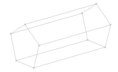
Nice box, but, with only edit points at the corners, there is not much I can do with it. I need to add more edit points. Since the box is made up of NURB surfaces that can be curved, how do I add more shape controls? Each face of the box is one NURB surface made up of two rows and two columns – a 2X2 grid of points. I can move any of the four corner points, but that won’t give me much of a curved shape. To add more shape control to a NURB surface, Pilot3D allows you to add in additional rows or columns. (NURB surfaces always have to maintain this rectangular grid of edit points organized into rows and columns.)
To add another row or column into a surface, you need to use the Surf-Add Row/Col-Add Row/Col Angle command and pick a point near the middle of any line on the box. For the example below, I picked a point near the middle of the top edge of the box. Notice in the example that the new column goes all the way around the box and adds a new column to each of the surfaces. This is done to maintain the bonded (watertight) edge criteria for the box. This command adds in four more edit points and opens up a lot more possibilities in shape. Note that I added the new column near the middle of the box. I could have added it in anywhere, but NURB surfaces have nicer shapes if you add your new rows and columns by splitting the distance between existing rows and columns.
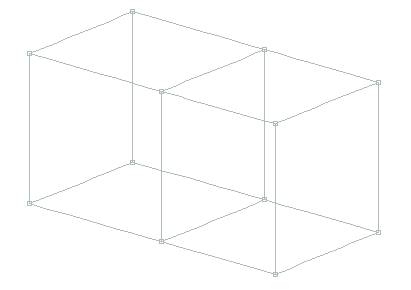
With 12 edit points, I can start creating some interesting shapes. To move any of the edit points, use the Move Point command on the toolbar or the Edit-Move Point command. There is a Move Point % command that can be used for more complicated surfaces that require fine-tune shape control. (See the separate tutorial on detailed surface shaping and fairing.)
This is the same box with the top two middle points moved. This can be done in the 3D view or in any one of the standard right angle views. Note that if you make any mistakes, you can always use the Undo command on the toolbar (the counter-clockwise arrow). As you are editing the box, keep in mind that it is a completely closed object with surfaces on all sides. None of the surfaces will separate when you move any point.
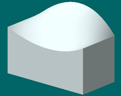
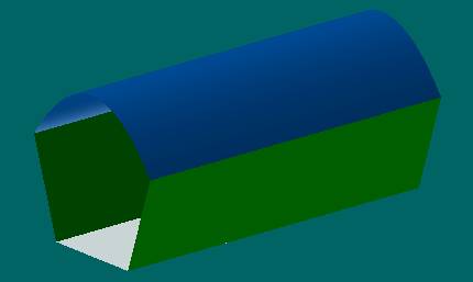
This is the rendered view of the object.
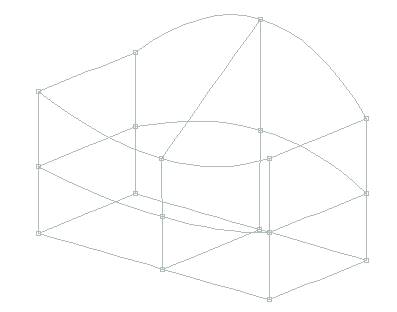
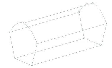
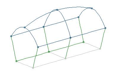
With these 12 edit points, there are many more
shapes that can be defined. This is
just the start, however, since you can add in any number of additional rows or
columns. Use the same Surf-Add Row/Col-Add Row/Col Angle command to add in a
row (horizontally) in the middle of the box. You do this by picking a point in
the middle of a vertical column of the box. The next picture shows the shape
after adding in the row. Now we have 18 edit points on the box.
You have to be careful with this add row/col
process. First, when you add in a new row or column, you should make sure you
insert the row/col halfway between two existing rows or columns. This is not
mandatory, but the NURB surfaces look nicer that way. Second, each time you add
in a new row or column, move the edit points to get the shape close to what you
want. This is a lot easier that adding a bunch of rows and columns first and
then trying to get the shape you want.
With 18 edit points on the box, you now have some real flexibility in shape.
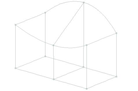
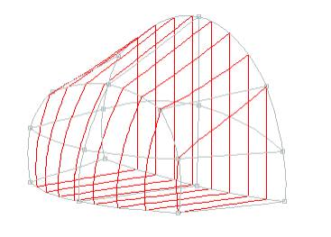
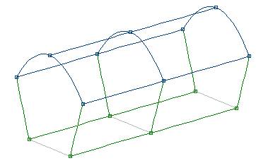
To evaluate the design, you can display any
cross-section cuts of the 3D shape. This picture shows a series of vertical
slices of the model. You can define and turn these cuts on in the PlaneCuts
section of the program. If you want, the program will dynamically redraw these
cuts while you are dragging the edit points. Perhaps there are some specific
measurement constraints that these sections will help you meet.
If you haven’t done so, try out the program, create
a box, add a couple of rows and columns and push the shape around. You can
create shapes that look nothing like a box.
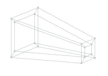
There are also many variations of the box shape that
can be created for the initial dialog box shape. There are options to change
the shape, location and orientation of the each end of the box. You can also
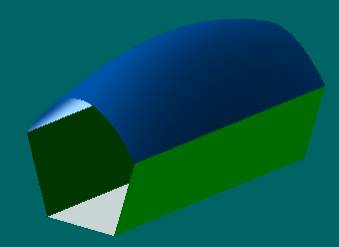
make the box hollow or have a specified thickness, as shown below.
This is a tapered, hollow box that was created from
the original “box” definition. You have control over all of the dimensions.
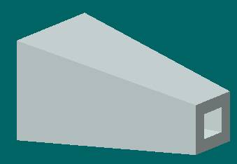
This is the rendered view of the shape. Just like
the simple box, this starting shape is completely bonded and watertight. You can
also add in additional rows and columns just like before.
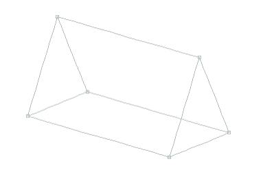
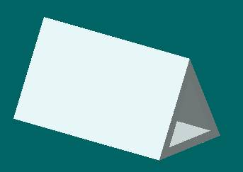
A different type of building block shape is the
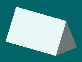
triangle solid. Below is the most simple form of that shape.
This is its rendered view.
This is the same triangle shape, but with a user-defined thickness. Remember that all edges are bonded and watertight. This means that you can move any of the edit points and be assured that the object will not come apart.
Just like the box example, you can use the Add
Row/Col Angle command to add in additional edit shape controls.
The Cylinder/Cone basic building shape also allows
you to define a thickness and change the shape and dimensions of each end.
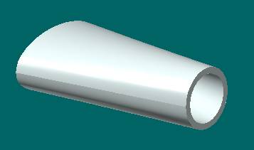
You can also specify a start and stop angle for the shape.
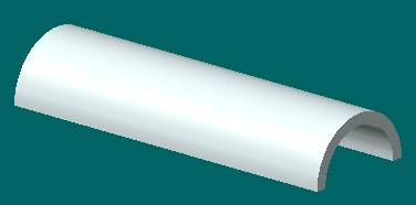
This
is a half-cylinder that has all edges bonded
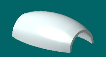
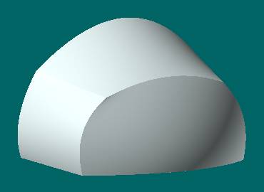
This is a portion of an ellipsoid that has thickness and is capped off on all edges.
This covers the basic 3D building block shapes, but there is much more you can do, starting with the 2D curve shapes: triangle, rectangle, trapazoid, arc, circle, ellipse and polygon.
The polygon is an interesting starting shape. You can go to the Create 2D-Polygon set of commands and create a simple polygon, like the pentagon. Then, you can use the Create 3D-Extrude command to convert it into a five-surface object. In this case, the ends are not closed off with surfaces.
One trick you can do is to join two surfaces into
one with the Surf-Cvt Row/Col Knuckle command. This command will change a
surface edge between two surfaces into a smooth edge. This really just joins
the two surfaces into one, smooth surface.
This is the result.
You can also add rows or columns just like for the
other basic building block shapes. Here, a new column is inserted in the middle
of the rounded-top pentagon.
Like before, you can use the edit points on the
surfaces to modify the shape.
With a few basic shapes and 3D modification
concepts, you can create a huge range of interesting curved surface shapes.
An additional advantage of the watertight bonding
technique we use is that the model will import into solid modeling programs
with no problems. The edges are guaranteed to be mathematically the same.
There is a whole lot more to Pilot3D than what is
described here – trimmed surfaces, developed surfaces, construction templates
and patterns, and more. The purpose of this tutorial is to give you a fast way
to get started.