Bonding Surface Edge Tutorial
Introduction
Most surface design programs
use B-spline or NURB surfaces to define curved shapes. Each surface entity is
defined by a rectangular grid of “edit” points. For most CAD programs, the edit
points are the NURB vertex points that don’t lie on the surface, except at the
4 corner points. The edit (vertex)
points just influence the shape of the surface. ProSurf (Pilot3D), on the other
hand, fits or interpolates the surface through these edit points. The floating
vertex points are calculated, but they are hidden. Either way, a single NURB
surface entity is defined by this grid of points. The rows and columns of this
grid are often connected by lines. If the edit points are the floating edit
points, then this grid is called the vertex mesh. To see the shape of the
surface, the program has to draw the associated lines on the surface. For our
interpolated approach, the points are on the surface and all you need to see
are the row and column grid lines on the surface.
The reason this is brought
up is that these defining edit point rows and columns are important. They
define the mathematics used for that surface. They also influence how you can
connect surfaces together. Most objects are not made up of just one NURB
surface. NURB surfaces are defined by their rectangular grid of points and
although you can move those points to any position or shape you want, the shape
is smooth and controllable only for simple variations of a rectangular shape.
This means that you have to break a larger, complicated surface into areas of
connected, rectangular (and triangular)-like NURB surfaces. You can also create
non-rectangular surface shapes by trimming off portions of a NURB surface, but
that discussion has to wait for another tutorial.
Most of the time, you want
to connect two NURB surfaces together so that they match up exactly
edge-to-edge. The two surfaces do not have to be smoothly connected, but they
need to form a “watertight” connection. This means that the two NURB surface
edges match up mathematically exactly. If you zoom in, you will see no gaps.
This is important for construction and for sending the model to solid modeling
programs. Solid modelers can cover tiny gaps between surfaces, but it can cause
problems later on.
The real problem with
connected NURB surfaces is the design process. Most CAD programs call connected
surfaces polysurfaces. This is kind of like a polyline, which is a group of
connected line segments defined as one entity. The programs allow you to
connect the surfaces together at an edge, but you cannot edit their shapes
without “exploding” (disconnecting) the surfaces. This means that when you move
one common surface edge, the other (matching) surface edge does not move along
with it. This makes life very difficult for designing connected NURB surfaces.
ProSurf (Pilot3D) gets
around this problem by setting up geometrical relationships or constraints
between surfaces. The relationships are optional and are defined separately
from the geometry. We call it bonded surfaces or edges. Once two surface edges
are bonded, they can be edited and remain attached. They can also be un-bonded,
if necessary without deleting the surfaces. The only requirement for bonding
is that the two adjoining surface edges must meet up with the exact same number
of defining grid rows or columns. Otherwise, the program cannot guarantee
that the two surfaces meet mathematically exactly (watertight) at the common
edge. ProSurf (Pilot3D) has joining methods for other cases, but it can’t
guarantee watertight connections. For those cases, the connections may be
within building tolerances.
Bonding Surfaces
Let’s start with the
simplest case; joining two very simple NURB surfaces. We will create two simple
four corner (two rows and two columns) NURB surfaces and join (bond) them
together.
1. Start up the program.
2. Select the Surf-Add Surf
command.
This command allows you to
define a simple 4-corner surface by picking 4 defining edit points on the
screen. Enter the points as rows (back and forth), rather than clockwise or
counter-clockwise. Do this twice to create two very simple NURB surfaces
side-by-side, as follows:
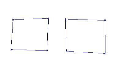
This shows two (simplest)
NURB surfaces, side-by-side. Before I can bond them together, I have to move or
match up the edge points of one surface with the other. ProSurf (Pilot3D) has a
special command for this.
3. Select the Edit-Match
Point-3D Match command.
This command wants you to
first pick the point you want to move and then pick the point you want it
matched up with. Do this twice to match the surface column points on the left
surface to the ones on the right. It should look like this.
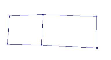
Note that these points are
only matched up and can be separated. The edges are not automatically bonded.
Try moving a point to see what happens.
4. Select the Edit-Move
Point command (on the toolbar too) and move one of the points, like this.
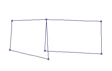
The points were matched up,
but the surfaces were not bonded. (There is also mand to “Merge” points, rather
than match points, together. Merging defines a constraint relationship between
any two edit points so that they remain together when the point is moved. That
can be used for when bonding is not appropriate.)
5. Select the Edit-Undo
command (counter-clockwise arrow on the toolbar).
Now that the two surfaces
edge points are matched up exactly, point for point (only two in this case),
you can bond the surfaces together
6. Select the Surf-Bond
Edge-Bond Edge command.
This command wants you to
pick the common surface edge that you want to bond. It requires that the two
surfaces match up exactly, point-for-point along the common edge. Some
(including myself) have had difficulty with this command because sometimes two
points look exactly the same, but they are not. (One of the future changes to
this command is to look for points that are “close” together. In the mean time,
using the 3D Match command works fine.
To check to see if the Bond
Edge command really works, try moving an edge point.
7. Select the Move Point
command and move one of the points
You should see something
like this.
These are two separate NURB
surfaces that can now be edited without separation.
OK, but what happens now
when you want to add more shape to the surface(s)? This is normally done with
one of the Surf-Add Row/Col commands. When two (or more) surfaces are bonded
together edge-to-edge, the only way to maintain the mathematically perfect bond
when you add a row of column is to make sure you add the row/col across all of
the bonded edges.
8. Select the Surf-Add
Row/Col-Add Row/Col Angle command
This command allows you to
add a new row or column to a surface. This gives you more edit points and more
control over the shape of the surface. Pick in the middle of any of the
vertical columns of either surface. You will see the following.
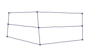
Notice that the program
checks for bonded edges and makes sure that the row (in this case) is added
across all of the bonded surfaces. This guarantees that a watertight
connection. If the surfaces were just matched up and not bonded, then the add
row/col command would add the row in only one surface.
To test it out, use the move
command to see what happens.
9. Select the Move Point
command and move the middle point of the bonded edge. This is what you should
see.
The two surfaces remain
bonded after the add row/col command.
For bonded edges, ProSurf
(Pilot3D) also allows you convert that edge back and forth between a hard or
knuckle edge and a smooth or curved edge. For a hard or knuckle edge, the
program uses two separate NURB surface entities. When you use the command to
convert it to a smooth edge, the program combines the two surfaces into one
NURB surface. This also means that this “knuckle” command works (or toggles)
both ways. It means that you can use it on any internal row or column of an
existing surface. The program will split the one NURB surface into two separate
NURB surfaces along that row or column, AND that the two surfaces will
automatically be bonded. You do not have to do the bonding. The program does it for you.
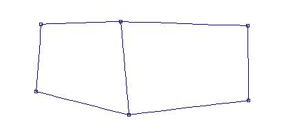
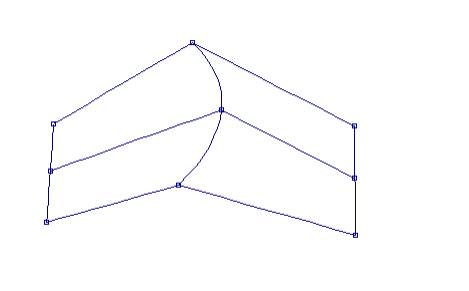
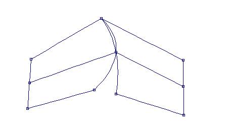
10. Select the Surf-Cvt
Row/Col Knuckle command.
Pick the common bonded edge
to create the one, smooth NURB surface show below.
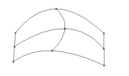
On the other hand, if you
think of this as a single NURB surface (that came from ProSurf or any other
program), then you can split it into two separate NURB surfaces along any
internal row or column. The program will split the surface and make sure that
the common edge is bonded.
11. Pick the middle column
again.
This will convert the one
surface back into two, where you started. Try this command on any internal
row/col of any surface. Click once to convert (toggle) one way, and click again
to convert back where you were.
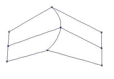
The picture below shows you
back where you started from.
In some cases, you want to
separate two bonded surfaces. You can un-bond the surfaces, if you want.
12. Select the Surf-Bond
Edge-UnBond Edge
Pick the middle, bonded
edge. The status line says that you are done, but the shape doesn’t change. Use
the Move Point command to check it out.
13. Select the Edit-Move
Point command and move one of the common points.
You will see that only one
of the points move, as seen below.
This covers a quick
introduction to joining and bonding surfaces. The only warning is to be careful
about all of the constraints you place on a model. The downside of parametric
or constraint-based modeling is that you could constrain yourself into a
corner. You could have so many relationships defined that making larger changes
late in the design cycle is very difficult. For ProSurf (Pilot3D), however,
constraints are optional and can be removed without deleting the geometry.