Pilot3D Tutorial
On Fairing
Curves and Surfaces
Copyright 2001, by New Wave
Systems, Inc., All Rights Reserved
Fairing Overview
In spite of what you may have heard, these two
statements are true:
1.
There is no mathematical definition of fairness.
2.
The fairness of a curve or surface is based on human interpretation and
judgement.
This does not mean that everyone would disagree on
the fairness of a curve or that there are no mathematical tools to use to check
for bumps and wiggles. It just means
that there are no good ways to automatically fair a curve or surface by
computer without some form of human input.
Let’s start by examining the traditional fairing
process on the drafting board or on the loft floor. The first tool of fairing is the large size of the drawing and
the use of the human eye. Given a large
enough drawing, the human eye can easily pick up subtle shape changes (within
building tolerances). There is nothing
like putting your head near the drafting table and sighting down along the
curve.
For the traditional lines drawing process, there
are two interrelated processes taking place: fairing the curve and matching up
the three different views: front, top, and side views. Matching up the three lines views refers to
the process of matching up the shape of the different lines in the different
views. This matching up of the three
views is under the complete control (is the responsibility of) the designer or
the loftsman. Many times a designer
will fair a curve only to find that the three views no longer match and define
a legal object. Producing a usable
lines drawing involves matching up the lines in all three views AND making sure that the lines are
fair. This two-part process is what
makes lines drawing or lofting by hand so difficult.
Using a computer program for defining and fairing
an object, however, removes the matching problem. This is because the program defines the complete surface
mathematically using something akin to a stretchable rectangular-like spline
membrane. If you pull the surface in
one direction, the surface is updated in all three views. The program can “cut” the surface at any
time to determine the shape of any of the lines, and there is a guarantee that
all of the lines match in all of the views.
The only thing that a computer design program
cannot do is to automatically shape and fair the curves and surfaces of the
object. It doesn’t know what a good
shape is and it doesn’t know what a fair shape is. Therefore, it is up to the designer using the program to define a
proper shape and make sure that the shape is fair. The big benefit of the computer program is to eliminate the
view-matching problem. This makes it
much more easy for users to design accurate surface shapes (the lines are
guaranteed to match in all views).
Some design programs insist that there is no need
for fairing because the surface is automatically fair. This can only be true if the program
severely limits the range of shapes that can be defined. It is kind of like defining a curve using a
batten and only three ducks. It is
virtually impossible to create an unfair curve with this limitation, although
it is also impossible to create anything but the most simple of shapes. With a computer program, the tools may be
fancier, but the limitation is the same.
You don’t get automatic fairness for free.
If the computer program does not fair the shape,
then how do you smooth a surface on a small computer screen? For traditional drafting and lofting, you
can use a number of the following techniques:
1.
Examining a large curve by eye
2.
Fore-shortening the drawing in the long direction
3.
Lifting a duck from the batten to “relax” the curve
shape
The most important fairing technique is examining
the curves by eye. On a small computer
screen, this is impossible. It is
aggravated by the “jagged” display of the curves due to the resolution of the
screen. Some designers hope for a large
(6 foot) flat panel computer screen to replace their traditional drafting
board, but it is quite unlikely to see this in the near future or for any
reasonable cost.
If you cannot use your eye to fair a curve or
surface on the computer screen, what can a surface design program do? Although there is no mathematical definition
of fairness, many feel that the use of second derivative or curvature
techniques hold the solution. These two
techniques are variations of each other since curvature is based on the second
derivative of a curve or surface. What
these techniques do is to magnify and define all of the bumps, wiggles, and
inflection points of a curve or surface so that the designer can alter the
surface shape to achieve his/her own criteria of fairness. What would be an invisible unfairness of the
lines of the surface on the computer screen, become clearly visible when using
one of these derivative techniques. All
surface design programs approach this fairness magnification in different ways
and each technique greatly influences how easy it is to fair a surface.
Pilot3D uses a dynamic curvature curve overlay technique
that is felt to be the easiest and fastest fairing technique to learn and
use. It can be applied to both NURB
curves and NURB surfaces. A related
technique for surfaces is the coloring of the surface based on one of its
curvatures: Gaussian or mean curvature.
This tutorial will first discuss the shaping and
fairing of curves using the curvature overlay technique. Then it will discuss the shaping and fairing
of surfaces using both the curvature overlay technique and the Gaussian surface
curvature display.
Shaping and Fairing Curves
To understand how to use the curvature overlay
technique in Pilot3D, it is best to start by studying curves. The process is nearly the same for surfaces,
but it is easier to see when applied to curves.
Follow these steps:
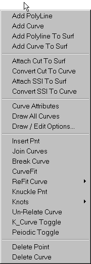
·
Start the Pilot3D program
·
Display the Curve set of menu choices as shown
above
·
Select the Add Curve function
·
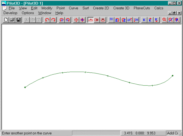
Pick (enter) about eight points to define a curve
like the one shown above
·
Space the points evenly along its length
·
Do not worry about fairness at this point
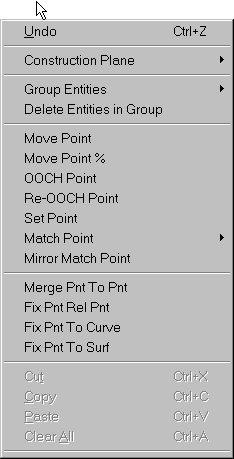
For rough fairing, you need to use the Move Point
command in the Edit set of pull-down commands as shown in the picture
above. All entities are defined by
points and all entities can be shaped (by eye) using the Move Point command.
·
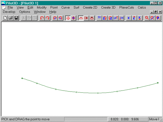
Use the Move Point command to change the curve into
a shallow bowl shape as shown in above
·
Try to maintain an even spacing of the points
·
Fair the curve by eye
As you can see, the curve achieves the fairest
shape when the points are evenly spaced.
This even spacing is not mandatory, but it is a good goal. Think of the traditional spline batten and
the spacing of the ducks along its length.
The ducks are evenly spaced, except for the areas of tighter curvature,
where their spacing is evenly reduced.
This works exactly the same for B-spline or NURB curves, since they are
mathematical equivalents of the draftsman’s spline.
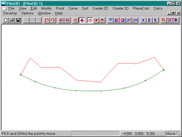
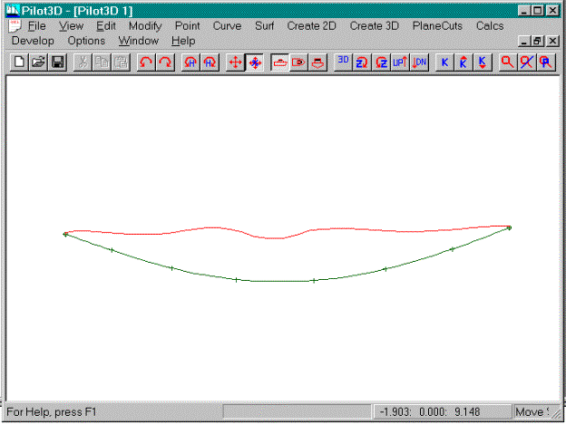
At this point, the curve may look fair, but there
is no way to know for sure, unless you plot it out full size and use your eye
to judge its shape. On the small
computer screen and with the “jagged” display of the curve, it is impossible to
fair using the Move Point command. You
could “Zoom In” until you have enough resolution, but only a part of the curve
will be visible to judge fairness by eye.
That is why Pilot3D provides a tool called the dynamic curvature curve overlay technique
to magnify the bumps, wiggles, and inflection points in a curve. It is turned on as follows:
·
In the Curve pull-down menu, select the K_Curve
Toggle command
·
“Pick” the defined curve.
[You can also use the ‘K’ toolbar button to turn
on/off the curvature curve for any curve or surface row or column.]
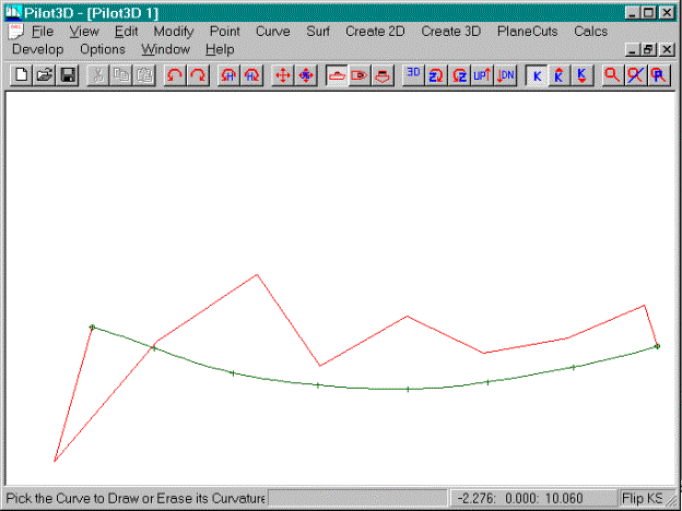
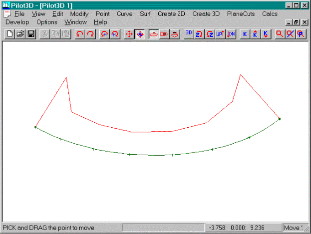
You should now see an orange curve drawn on top of
the defined NURB curve, something like the one shown above. The command is called a “toggle” because to
turn off the display of the k-curve, you simply pick the curve again with the
same command; once to turn it on and once to turn it off.
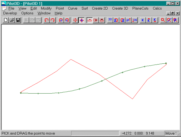
This curve (sometimes called a ‘K’ curve, since
many books use ‘k’ to represent curvature) represents the curvature of the
curve overlaid on top of the curve it represents. Its shape is very, very sensitive to the shape of the curve it
represents. Try the following:
·
Use the Move Point command to move one of the curve
points
·
See how a small change in point position causes a
large change in K-curve shape
(Note: you will learn about a fine-tune move%
command shortly which you will use to perform fairing.)
Key
points about the K-curve:
1.
The k-curve will lie on the inside, concave side of
the NURB curve.
[This can be flipped to
the other side of the curve, if you want.]
2.
The k-curve will cross the NURB curve at all
inflection points
3.
If the NURB curve is exactly flat, then the k-curve
will lie on exactly top of the NURB curve
4.
If you make the k-curve reasonably smooth, then the
underlying NURB curve will be very fair.
5.
The shape of the k-curve is important, not its size
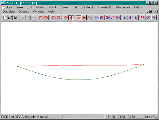
Sometimes, the k-curve is so large that it is drawn
off the visible part of the window. The
size of the k-curve can be reduced (but not its shape) by using the downward
‘K’ arrow on the tool bar. Every time
you “click” this toolbar button, the magnitude of the k-curve is reduced. The picture above shows the same k-curve
after the K-down toolbar button has been picked three times. Be careful not to reduce the magnitude of
the k-curve too much, because you will reduce its sensitivity to the unfairness
of the NURB curve.
·
Click the K-Down toolbar button three times
·
Click the K-Up toolbar button three times
Likewise, if the k-curve is drawn very close to the
NURB curve itself, you may wish to increase its sensitivity or magnification by
using the K-Up arrow on the tool bar.
It has the opposite effect and the K-down arrow.
·
Click the k-Up toolbar button three times
·
Click the k-Down toolbar button three times
So
how do you know when you have enough magnification of the k-curve?
You have enough magnification if the k-curve
visibly changes shape when you move one of the defining points by the building
tolerance (perhaps 1/32 of an inch or one mm).
The distance a point is moved is always dynamically displayed in the
status line while you are dragging the point.
If the magnification is set too low, then the k-curve will not show
unfair changes in the shape of the NURB curve.
If the magnification is set too high, then the k-curve will be drawn
outside the window and will be overly sensitive to editing changesand will be
difficult to smooth. Note that with
enough magnification, you could fair the curve to within 1/1000th of
an inch. Keep in mind that there is no
such thing as perfect fairness. You
only have to fair the curve to within building tolerances. However, it is preferable to err on the side
of too much magnification, rather than too little.
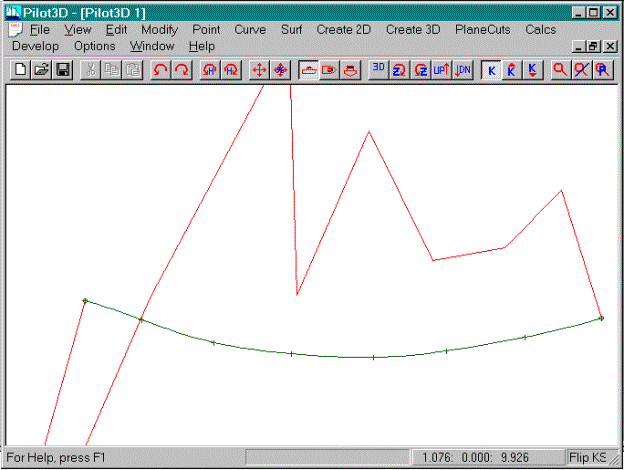
For those who are interested, this picture shows
how the k-curve is calculated. The
process is as follows:
At each defining point, the program:
1.
Calculates the curvature value of the NURB
curve. Curvature is the reciprocal of
the radius of curvature of the curve at that point. (k = 1 / rho) The
curvature is zero when the curve is flat, increasing in value as the curve
becomes more rounded.
2.
The normal vector of the curve at that point is
calculated.
3.
A k-curve point is determined a distance along that
normal vector from the NURB curve.
4.
The distance along that normal is equal to the
curvature value times the k-curve magnification factor.
5.
A polyline is drawn connecting the k-curve points
of each defining point.
The magnification factor adjusts the scaling of the
k-curve and does not change the character of its shape.
[Note: A more exact curvature curve display is show
later in this tutorial.]
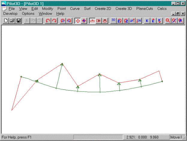
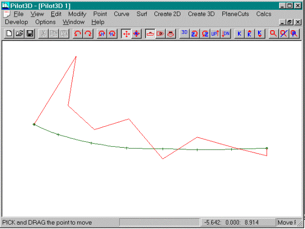
This screen shows two arrows pointing at two
adjacent defining NURB points. The
curve in the area of the left arrow is relatively flat, because its k-curve
point is closer to the NURB curve than the k-curve point at the right
arrow. If the goal of fairing is to
smooth the k-curve, you could approach this problem in one of two ways. One, you could pull the left-arrow curve
point away from the k-curve to create more curvature and cause the k-curve to
move away from the NURB curve. (Move the NURB curve in a direction opposite to
the direction you wish to move its k-curve point, but wait until the fine tune
Move% command is introduced, since you won’t have enough control with the Move
Point command.) Two, you could move the
right arrow point towards its k-curve point.
Remember that many different curve shapes will create a smooth k-curve
shape. You, the designer, have to
decide on the shape you want and use the k-curve to guide you with the final
fairing. If you wanted the curve to be
rounded in that area, you would move the left arrow point. If you wanted the curve to be flatter in that
area, you would move the right arrow point.
This same kind of problem arises with the
traditional hand drafting approach using a batten and ducks. One way to fair a batten is to temporarily
lift one or more of the ducks, thereby relaxing and fairing the batten and the
resultant curve. If this technique is
done too often, however, the batten will be designing the surface rather than
the designer.
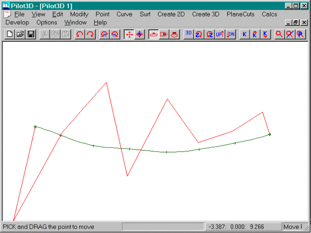
This screen shows a typical k-curve shape for a
NURB curve that has inflection points, one of which is marked by the cursor
arrow. Many times this is a clear
indication of an unfair spot on the curve, although some curves (like S-shaped
curves), are supposed to have inflection points. The goal is not to get
the k-curve to lie on one side of the NURB curve, the goal is to smooth the
k-curve. This means that the underlying
NURB curve is very fair.
Use the “saw-tooth” up-and-down nature of the
k-curve to determine how to fair the curve.
Look for a k-curve point that is a valley between two peaks or for a
k-curve point that is a peak between two valleys. In the picture above, the point to the left of the cursor arrow
has a k-curve point that is a valley between two k-curve peaks. If you move that point down, its k-curve
valley will disappear and the two surrounding k-curve peaks will be lowered,
thereby smoothing the overall k-curve.
With a little bit of practice, you will be able to quickly fair a curve.
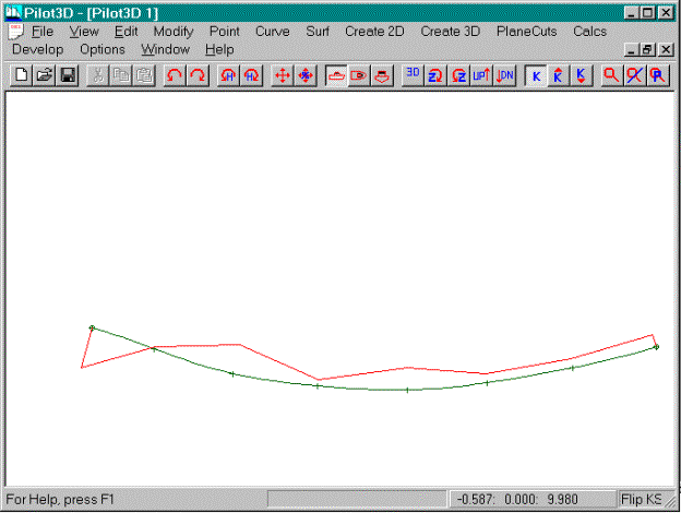
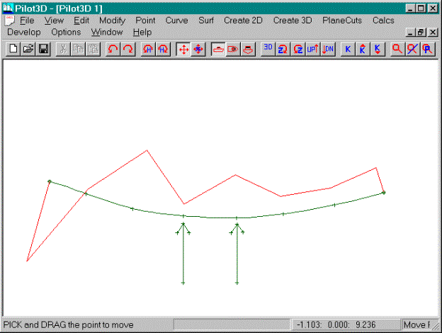
To flatten out a NURB curve, you need to get the
k-curve to lie exactly on top of the NURB curve. This picture shows the results of flattening the curve using just
the Move Point command. It is not very
exact because the standard Move Point command is too coarse of a modification
tool.
·
Turn on the Move Point command
·
Adjust the shape of the curve by eye to obtain a
flat portion like that shown above
Detailed
k-curve fairing is done using the Move% command in the Edit set of pull-down
commands. The Move%
command works exactly like the Move Point command, except that when you drag
the point on the curve, the point only moves a small percentage (1%) of the
distance in the direction you drag the cursor.
When this is done with the k-curve turned on, you can dynamically and
accurately control the shape of the k-curve.
·
Turn on the Move% command in the Edit set of
pull-down commands
·
Adjust the curve (just like using the Move Point
command) to obtain a flat portion
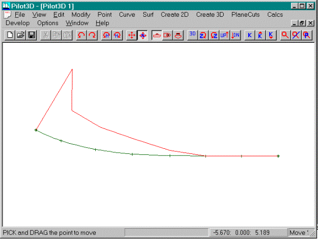
The picture above shows the results of flattening
and fairing the curve using the Move% command.
If you think that the k-curve moves too much for a very small change in
curve shape, then you probably need to use the k-Down toolbar button to reduce
the sensitivity and magnification of the k-curve.
This picture shows a different curve shape, faired
by eye using the Move Point command.
·
Select the Move Point command
·
Edit the curve by eye to get the shape shown in the
picture above.
At this point the curve is only roughly faired by
eye.
·
Select the Move% command
·
Fair the curve as shown in the picture above
This picture shows the same curve after fairing was
performed using the Move% command. Note
the peaks in the k-curves at the ends of the curve. Otherwise, the k-curve (and NURB curve) is very fair. The peaks in the k-curves at the ends
indicate that there is a non-zero curvature at each end of the curve. It doesn’t necessarily mean that the curve
is unfair. It depends on what kind of
shape you want at the ends of the curves.
A different end condition is achieved in the following example.
·
Select the Move% command
·
Fair the curve as shown in the picture above
This picture shows a slight variation of the curve
with no k-curve peaks at the ends. The
k-curve matches the NURB curve in the ends which means that at those points the
curvature goes to zero.
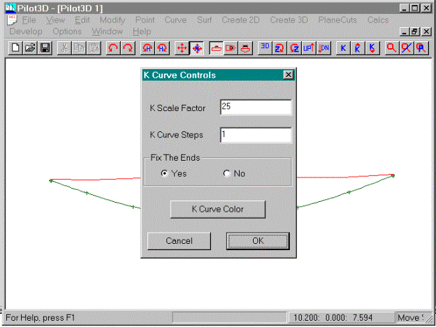
This picture shows the Options-Set K_Curve dialog
box for k-curve options. The “K Scale
Factor” magnification factor relates to the K-Up and the K-Down toolbar
buttons. The “K Curve Steps” field
refers to the number of intermediate steps along the NURB curve to calculate
the curvature. The default is 1 which
means that the curvature curve is calculated and drawn at each defining
point. If this value is set to 2, the
program will calculate and display the curvature at each defining point and at
each intermediate position between defining points. For a value of 3, then there will be two intermediate k-values
calculated and drawn between defining point, and so on.
·
Open the Options-Set K_Curve dialog box
·
Set the “K Curve Steps” field to 5
·
Pick the OK button
You will now see a more accurate curvature curve
drawn, like the one shown above. The
k-curve is smooth, but one might wonder if the two k-curve “humps” should be
removed. Try it and see what happens.
·
Select the Move% command
·
Move the defining points to try and remove the
“humps” in the k-curve
It can’t be done, or at least, not very
easily. As you might guess, the exact
shape of the curvature curve is not always important for fairing. What is important is that the k-curve does
not have any abrupt changes or unwanted inflection points. As you increase the step size above 1, the
k-curve takes on a more accurate shape, but it actually makes it more difficult
to fair the curve. That is why we
recommend that the step size be left at 1.
Since you can only control the shape of the curve
by moving the defining points, you only need to display the k-curve based on
the curvature calculated at those points.
By increasing the step size and drawing a more accurate k-curve, you
confuse the fairing process by displaying k-curve shape that you have no
control over. For NURB curves and
surfaces, you can also control the shape by changing the “knot
parameterization” or the “weight values”.
These changes are not discussed here.
·
Select the Options-Set K_Curve dialog box
·
Set the step size to 1
This picture shows a faired k-curve for an S-type
of NURB curve. Remember that the
inflection point is defined as the place where the k-curve crosses the NURB
curve.
·
Select the Move Point command
·
Move the curve points to create the rough S-shape
·
Select the Move% command
·
Drag (fine tune) the points to smooth the k-curve
as shown in the picture
·
Select the Curve-K_Curve Toggle command
·
Pick the NURB curve to turn off the k-curve display
Do all rough shaping with the Move Point command
and do all fairing with the Move% command.
Now you are ready to tackle the fairing of
surfaces. The k-curve technique is the
same, but it is applied to one or more of the rows and columns of the surface.
Shaping and Fairing Surfaces
This section discusses the shaping and fairing of
generic surfaces. It is assumed that you have gone through the
material in the previous section on shaping and fairing curves, since many of
the topics discussed there will be applied to surfaces.
Since we will be creating, shaping, and fairing
surfaces, you will need to use the commands listed under the “Surf” pull-down
list of commands, as shown in the figure above.
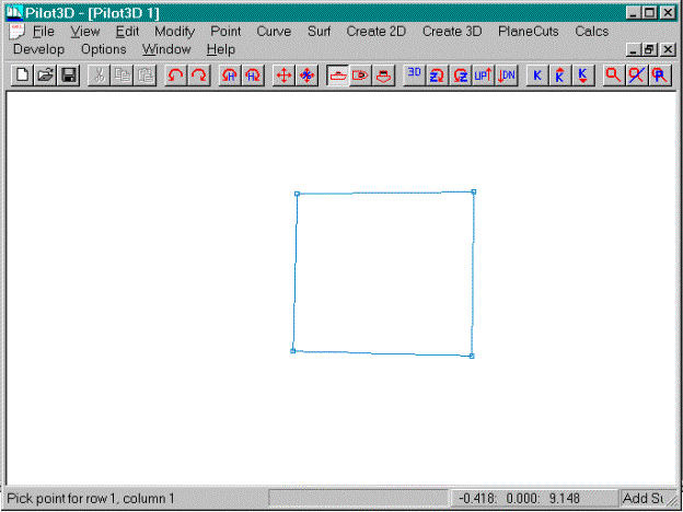
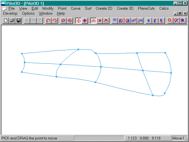
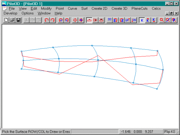
Start by adding a simple surface to a blank screen,
as shown above.
·
Select the “Add Surf command in the Surf pull-down
list of commands
·
Pick the four corners of the surface - lower right,
lower left, upper right, upper left
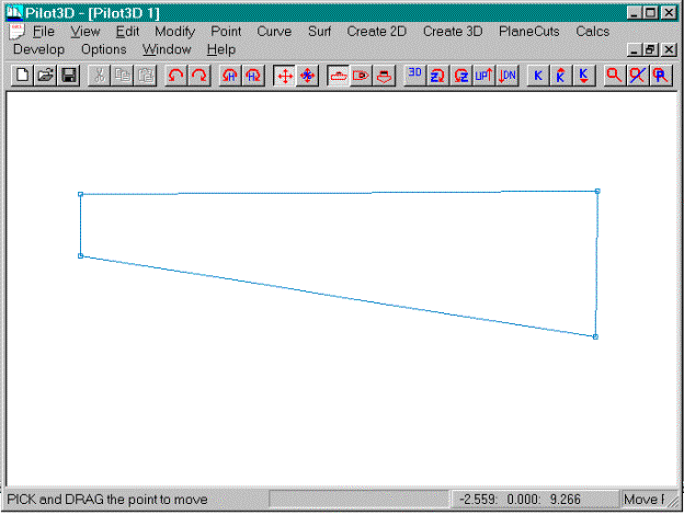
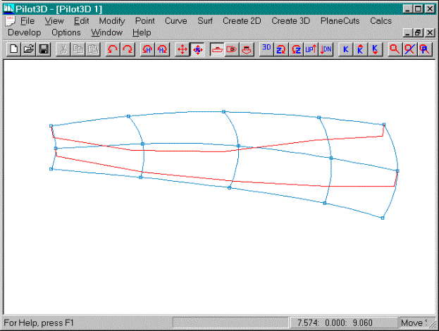
Change the shape to match the one shown above.
·
Select the Move Point command in the Edit pull-down
list of commands
·
Move the point to get a shape like the one shown
above
This is an arbitrary shape used only for
demonstration.
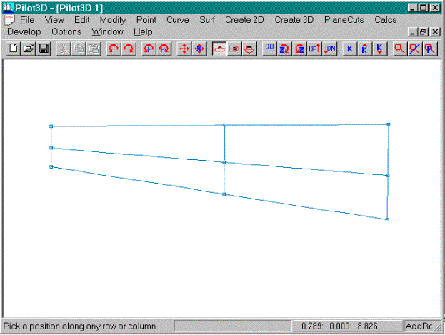
Add one row and one column to the surface.
When you create a new NURB surface, you enter the
corner points by rows. This defines the
orientation of the surface relative to its rows and columns. In general, however, you do not have to
worry about what are really rows and what are really columns of the
surface. All of the surface commands
work for either rows or columns. For
the clarity of this tutorial, we will refer to horizontally oriented surface
curves as rows and vertically oriented curves as columns, even though
internally, the rows and columns might be oriented otherwise.
·
Select the Surf-Add Row/Col-Add Row/Col Angle
command
·
Add a row by splitting the distance between the two
existing rows. Pick a location along
one of the columns about half-way between the two rows.
·
Add a column by splitting the distance between two
existing columns. Pick a location along
one of the rows about half-way between the two columns.
As a rule, always try to add a row or column by
splitting the difference between two existing rows or columns. You might end up with more row or columns
than you think you might need, but the additional lines will help greatly with
the shaping and fairing process.
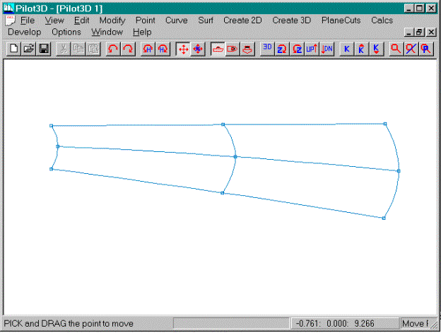
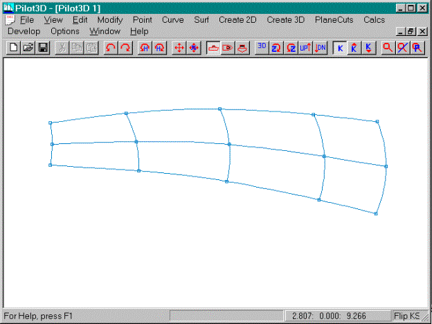
After you add one or two rows and columns, use the
Move Point command to roughly shape the surface by eye. This is a much better approach than adding
in a bunch of rows and columns before you begin any rough shaping of the
surface. Don’t worry yet, however,
about fairing the surface with the k-curve.
This will be done after a number of rows and columns have been added and
the rough shaping has been completed.
·
Select the Move Point command from the Edit set of
commands
·
Move the surface points to get a shape like the one
shown above.
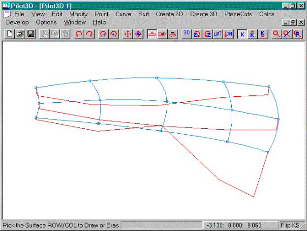
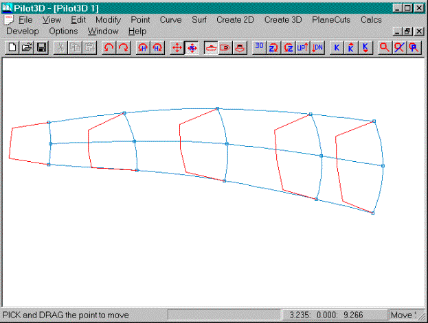
Now add two more columns to the surface, as shown
above.
·
Select the Surf-Add Row/Col-Add Row/Col Angle
command
·
Add two more columns by splitting the distance
between two existing columns, like in the picture above
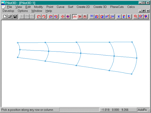
As mentioned above, it is always best to add new
rows and columns by splitting the difference between two existing rows or
columns. This keeps the rows and
columns fairly evenly spaced, which will help the shaping and fairing
process. If you don’t keep the rows and
columns evenly spaced, you might end up with a surface like the one below.
This surface was created by moving some of defining
points to create unevenly spaced rows and columns. This demonstrates some of the odd shapes that can happen when the
row and column spacing is not even.
Please note that the spacing does not have to be completely even. We generally suggest that the spacing
between rows or columns not be anything greater than a 2:1 ratio of
spacing. This means that if you have
two columns one foot apart, then the “next” column should be no more that two
feet further away, or less than ½ foot away.
This spacing rule will be met if you always add rows and columns about
one-half way between two existing rows or columns.
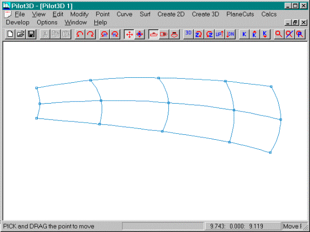
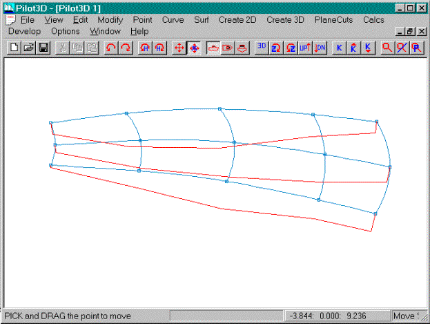
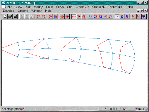
This picture shows the final, rough shape of the
surface. (This is an arbitrary shape
used only for this demonstration.)
·
Select the Move Point command
·
Move the surface points to match the surface in the
picture above
·
Only fair the surface by eye using the Move Point
command
Now that the surface has been roughed into
approximately the correct shape, the fairing can begin using the dynamic
k-curve overlay technique.
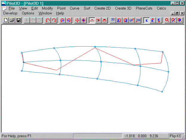
This picture shows the surface with a k-curve
turned on for the top row. (If you
haven’t done so already, please review the previous section on fairing curves
before you continue. This section
assumes that you understand some of the topics discussed there.)
·
Select the Surf-K_Curve Row/Col command
·
Pick the top row of the surface (pick the row
somewhere away from a defining point)
·
If the k-curve appears too large (magnified), you
may wish to use the K-Down toolbar button to reduce the magnification of the
k-curve
Note that your k-curve may not match the one shown
above, because the k-curve is very sensitive to the shape of the surface.
The goal of this tutorial is to fair this surface
using the k-curves, starting with the top row. The shape we want for the rows is slightly curved on the left
and fairly flat on the right. This is
shown above in that the k-curve for the row is drawn away from the curve on the
left and drawn on top of the row at the right (which means that it is flat in
that area). Remember that you are the
designer. Do not let the fairing
process define the shape of the surface.
·
Select the Move% command
·
Move% the points in the top row to achieve the
k-curve shape shown above
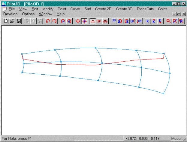
Now turn on the k-curve for the middle row and
leave on the k-curve for the top row.
·
Select the Surf-K_Curve Row/Col command
·
Pick the middle row of the surface
Use the Move% command to fair the shape of the
middle row and use the top row k-curve shape as a guideline. You want to avoid the mistake of fairing the
rows and columns of the surface without regard to the shapes of the surrounding
rows and columns. The k-curve shapes of
two consecutive rows or columns must be relatively the same.
·
Select the Move% command
·
Move% the points of the middle row to get the shape
(row and k-curve) shown above
Note that the shape of the middle row k-curve is
very close to the shape of the top row k-curve.
Now turn on the k-curve of the bottom row and leave
on the k-curves for the other two rows.
The screen is starting to get a little cluttered, but the different
color for the k-curves help them stand out.
·
Select the Surf-K_Curve Row/Col command
·
Pick the bottom row of the surface
Use the Move% command to fair the shape of the
bottom row and use the middle and top row k-curve shapes as a guideline. Follow the same process as before to shape
and fair the bottom row.
·
Select the Move% command
·
Move% the points of the botom row to get the shape
(row and k-curve) shown above
Note that the shape of the bottom row k-curve is
very close to the shape of the upper row k-curves.
Now that the rows have been faired, you can turn
off their display.
·
Select the Surf-K_Curve Row/Col command
·
Pick all three rows to turn off the k-curve display
Note that the same command is used to turn on and
off the display of the curvature curve lines.
That is why it is called a “toggle”.
Fairing the columns is not as important, since they
are defined with only three points, and are guaranteed to be fair
automatically. However, you want to make sure that all columns have the same
general k-curve shape. Remember that
you have to both fair the k-curves and make sure that consecutive row or column
k-curves have roughly the same shape, or at least, make sure that there is a
reasonable change in shape from one k-curve to another.
·
Select the Surf-K_Curve Row/Col command
·
Pick all of the columns to turn on their k-curves,
as shown above
·
Use the K-Down toolbar command to reduce the
k-curve magnification, if necessary
Note that the k-curves are all relatively fair, but
their shapes do not match very well.
This picture shows the results of moving points on
the middle row to make sure that all k-curves have the same general shape. Since all of the columns are part of the
same surface, you want them all to have the same characteristics. This doesn’t mean that the surface cannot
change its shape dramatically from one end to the other. It just means that you must pay attention to
the change in k-curve shape from one row or column to another.
·
Select the Move% command
·
Move% the points on the middle row to match up the
shapes of all of the column k-curves. Tip: If you move the points in a
direction tangent to the middle row, you will not (greatly) affect the fairness
of the rows themselves.
·
Move% the points to get the shape of the surface
shown above
This picture shows the final surface with all of
the k-curves turned off.
·
Select the Surf-K_Curve Row/Col command
·
Pick all of the columns to turn off the display of
the k-curves
Conclusion
This was a brief introduction to the process of
fairing curves and surfaces.
The following reviews the basic steps for creating
and fairing a surface.
1.
Create the basic surface.
2.
Position the surface in space.
3.
Rough out the topology or shape of the surface.
4.
Do some rough fairing (using Move Point) in all
views each time you add a row or column.
5.
Add in rows/cols by splitting the difference
between two existing rows or columns
6.
Once enough rows and cols have been entered and
roughly shaped, start on the detailed fairing (using the Move% and K-curve
commands) of the edges of the surface.
It is no use to fair the insides of a surface unless the edges are
exact.
7.
Use the K-curves to fair the interior shapes of the
rows and columns.
8.
Check sequences of K-curves to see if their shapes
match.
9.
Check the surface fairness using the Gaussian
curvature display.
Also, remember the following points:
·
A NURB surface is a rectangular-like grid of rows
and columns
·
It is more difficult to fair a distorted,
non-rectangular shape
·
Spread the rows and columns evenly over the surface
·
The fewer the rows and columns you use, the better
·
Keep the spread of rows and columns within a 2:1
spacing ratio
·
Rough shape the surface after adding each row or
column
·
Wait to fair the surface until after you have added
in all rows and columns
·
Use the K-curves on the rows and columns with the
Move% command
·
Turn on selected plane cuts to see them dynamically
change shape
·
Fair the surface only to within building tolerances
·
Use the Gaussian curvature display to check for
unfair spots
Fairing is not an automatic process and there are
different degrees of fairness. Keep in
mind that it is not necessary to fair a surface perfectly. All you have to worry about is getting the
surface fair to within building tolerances.