Surface Development and Layout
New! A very simple (one, two, three) plate layout example!
Pilot3D gives you an easy way to unwrap or layout your singly (developable) or doubly (expandable) curved surface. If a surface has too much double curvature, Pilot3D even gives you a way to subdivide the surface and unwrap the pieces. To learn more about the details of unwrapping developable and non-developable surfaces, see our white paper called "Plate Development and Expansion".
Unwrapping a surface is very simple. You just pick the surface to unwrap and the program displays the 2D pattern. This shape can be printed or plotted directly at any scale factor or it can be output to a DXF file to transfer to a CNC cutting machine program.


The top picture is a side view of a trimmed or notched surface and the bottom picture is its 2D developed pattern, including trace lines for a series of planar surface intersections. Pilot3D can even draw surface-surface intersection trace lines on the pattern.
If the surface has double curvature, Pilot3D will flatten it out into its 2D shape and give you information about the maximum stretch in the pattern. You can even tell the program how much perimeter stretch is allowed. The program can do this because it uses a finite element type of calculation where it solves a huge system of equations. Pilot3D does not use a simple triangularization and layout technique. It calculates all of the internal strains in the plate.
If you want to design a surface and make sure that it is developable (no double curvature), Pilot3D gives you the tools to do that easily. Other programs might give you information about the developablity of a surface (using Gaussian curvature, for example), but they don't tell you how to change the shape to make it developable. Pilot3D, on the other hand, uses our unique dynamic ruling line technique that recalculates the ruling lines while you are editing the shape of the boundary curves and colors them based on the amount of twist in the surface. This means that you can edit and smooth the surface edges and get immediate feedback on the developability of the surface. Once you have the edge curves and the ruling lines just right, Pilot3D will automatically fit a NURB surface through the set of ruling lines.


The top picture shows a 3D view of two NURB curves with ruling lines calculated and drawn in-between. Dark blue ruling lines indicate a developable shape that can be unwrapped without distortion. The other colors indicate higher levels of twist between the two curves. To correct the problem areas, all you have to do is use the Move Pnt and the Move Pnt% (this is the fine-tune move command) on the curve edit points and dynamically watch how the ruling lines and their colors change. It took a minute or so to correct the two curves to create one (in the middle) that has a nice spread of dark blue ruling lines. This means that the surface is completely developable. The bottom picture shows the 2D pattern generated from the NURB surface that was fit to the ruling lines. Also note that you can turn on the curvature fairing curves so that you can monitor the smoothness of the curves while you are creating a developable surface.
No other program in the world has this dynamic ruling line capability!
If you need to design complex surfaces that have to be unwrapped into 2D patterns, then Pilot3D makes your job very easy. You just define the edge curve shapes and Pilot3D takes care of the rest. No more guessing on ruling lines or using Gaussian curvature!


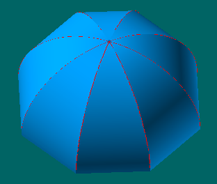
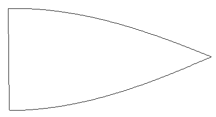
The top picture shows an octagon-shaped umbrella that could be made out of any flat material, like canvas. Each panel was created using ruling lines between the edge curves and fit with a NURB surface. The bottom picture shows the developed shape of one of these panels. The 3D model took about 10 minutes to create and the layout pattern took just one step. Then it is just one more step to output the shape to a plotter or a DXF file.

For another example, see the step-by-step tutorial on creating a half cone with a trimmed out star shape and see how it was flattened out.
Here are two more examples of surface creation and layout. Both start from digitized data. (See also the section on Reverse Engineering.) The first creates a surface with a cutout and the second creates and lays out a surface using only the boundary edge point data.

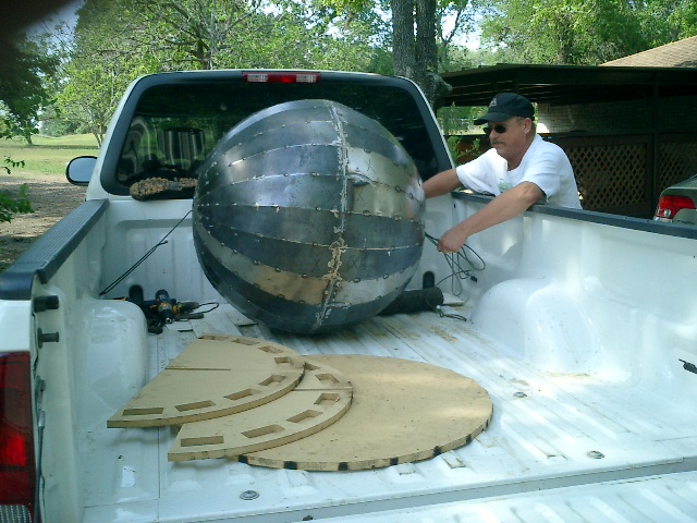
"The frame was drrawn in ProSurf 3 (Pilot3D) and edited in Shopbot's PartsWizard from DXF, then cut on Shopbot. The steel ball was drawn in ProSurf (Pilot3D), put in DXF and cut on a plasma table."
David Lemke, Victoria, TX